To complete this project you’ll need:
- Raspberry Pi Zero W or better.
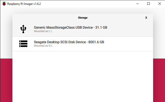
- MicroSD Card 8GB or larger.
- A free account at io.adafruit.com
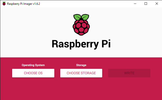
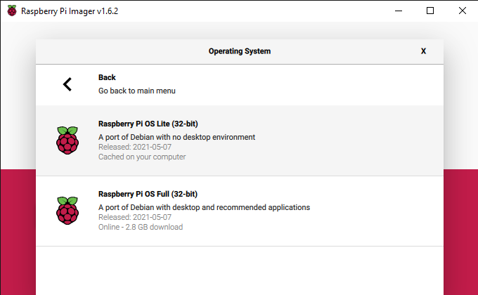
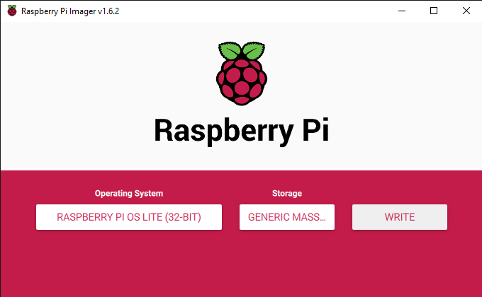
- Raspberry Pi Imager software.
- SDS011 sensor for measuring particulate matter.
- PuTTY or an equivalent tool for SSH communication.
- Wi-Fi available for the Raspberry Pi Zero W to connect.
Configure Your Pi Zero W
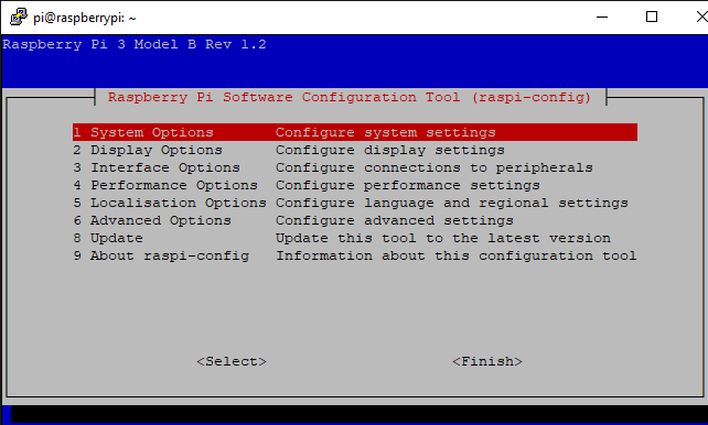
This project is just like Air Quality Project #1 so we’ll want to refer to the exact same steps for configuring the Raspberry Pi device, whether you’re using a Zero, 3B, or 4. The main difference, in my case at least, is that we’ll be following that 13th step and connecting to the WiFi because I don’t have a micro USB to Ethernet adapter for the Pi Zero W. If you don’t already have the Pi device configured feel free to refer back to “Raspberry Pi Air Quality Project #1” to follow the configuration section before continuing here.
Connect to your Raspberry Pi
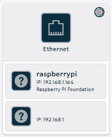
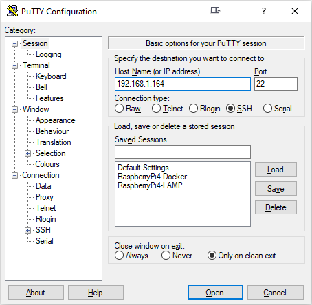
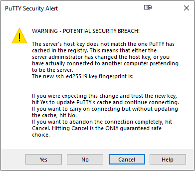
With your Raspberry Pi device connected to the WiFi, you can log into your router again, just like in Air Quality Project #1, to find the IP address of the Pi Zero. With that IP address, you can open PuTTY and create a new session and enter the IP address and default credentials for the Pi device.
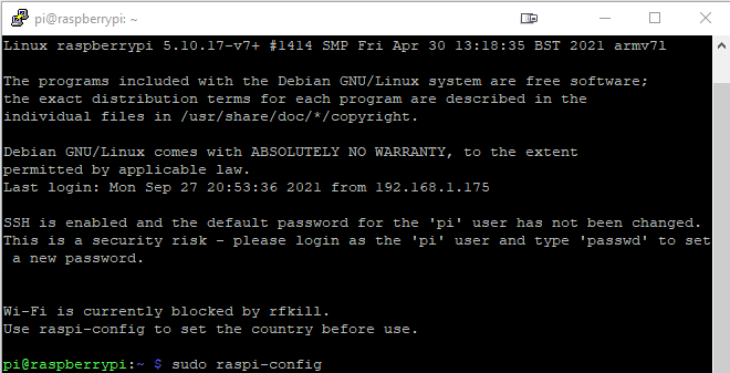
One thing you might notice when logging into the Pi Zero is that you’re on armv61 instead of armv71.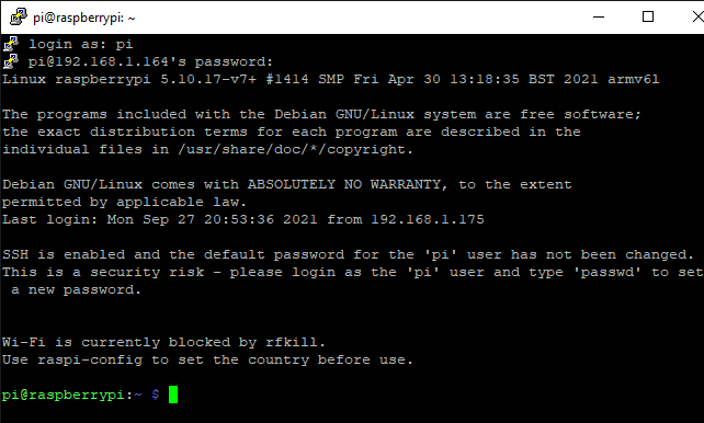
Additionally, if you’re noticing any lag while communicating with your WiFi-connected Pi Zero over SSH, you can directly connect a keyboard/mouse and monitor to your Pi Zero and enter the following command and reboot your Pi device.
echo "IPQoS 0x00" >> /etc/ssh/ssh_config && echo "IPQoS 0x00" >> /etc/ssh/sshd_configInstall the “pyserial” and “adafruit-io” Modules
In order to read the data from the SDS011 sensor we need to install the pyserial module and in order to push it to Adafruit.io we need the adafruit-io module.
You can install both of these modules with the following command,
pip3 install pyserial adafruit-ioIf you run into an error for not having pip3 you can install it with the “sudo apt install” command listed below. Once that is installed try again running the “pip3 install” command listed above.
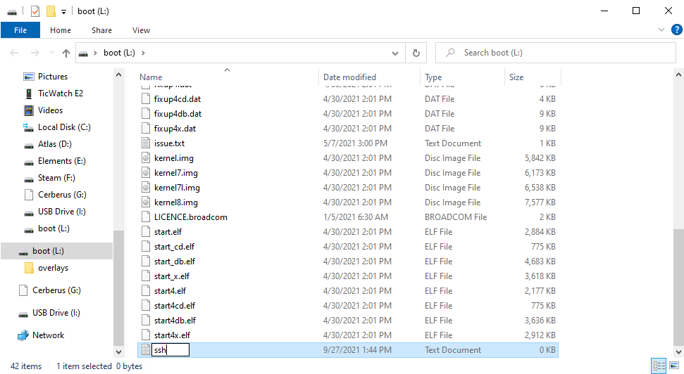
sudo apt install python3-pipWrite (or copy) a Python script to communicate with the sensor
For this part you can use whatever text editor you like but I’m going to use Nano because I’m already familiar with how to use it.
1. Create a directory for your script to live in and then navigate to it.
mkdir air_quality_monitor
cd air_quality_monitor
2. You can create your python script file by using the “touch” command.
touch aqm.py3. We can start editing the file by opening it in nano.
sudo nano aqm.py4. If you haven’t already, you’ll want to take a quick break and navigate over to io.adafruit.com and create your free account/login to get your Username and Key. From here you can copy the following code and customize it with your own Adafruit Username, Adafruit Key, and variable/feed names. Once you have it customized you can press Ctrl+X, then Y, then Enter to save your script.
import serial, time
from Adafruit_IO import Client
aio = Client('YourAdafruitUserName', 'YourAdafruitKey')

ser = serial.Serial('/dev/ttyUSB0')

while True:
        data = []
        for index in range(0,10):
                datum = ser.read()
                data.append(datum)

        pmtwofive = int.from_bytes(b''.join(data[2:4]), byteorder='little') / 10
        aio.send('aqmtwofive', pmtwofive)
        pmten = int.from_bytes(b''.join(data[4:6]), byteorder='little') / 10
        aio.send('aqmten', pmten)
        time.sleep(10)
5. With your script customized and saved, you’ll want to plug in your SDS011 sensor. Plugging this sensor into the Pi Zero may cause it to reboot, I know mine does. Once it has rebooted we can log back in and continue.
6. Navigate over to io.adafruit.com and login to your account. Follow these steps to create a dashboard and block for your data.
1. Click the "+New Dashboard" button. Give your new dashboard a name and description and click "Create".
2. Click on the "Gear" icon in the top right and click "+Create New Block", choose "Line Chart".
3. On the bottom of the "Connect Feeds" page where it says "Enter new feed name", enter the names you chose for the script, in this case it's "aqmtwofive" and "aqmten". So we'll type "aqmtwofive" and click "Create" then type "aqmten" and click "Create" again.
4. Check the box next to the two new feeds that you created and click the "Next step>" button in the bottom right.
5. On the "Block settings" page you can enter a "Block Title" and/or scroll down and click the "Create block" button.
This new block is going to be blank until we get our script going in the next steps.
7. With our data block configured on Adafruit, we can log back into our Pi Zero and start our Python script. If you’ve just logged back in and are sitting at the home directory, you can start your script as a background process by typing the following command.
python3 air_quality_monitor/aqm.py &If you run into any errors trying to start the script, make sure the Feed names match the names you chose in your script. Also, make sure the sensor is plugged into your Pi device.
8. Verify that your script is running with the following command.
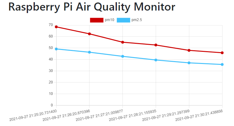
ps -ef | grep aqm.py9. With your script running you should see data starting to come in to your data block on your Adafruit dashboard. Again, if you’re not seeing any data you’ll want to make sure your feeds are set up correctly.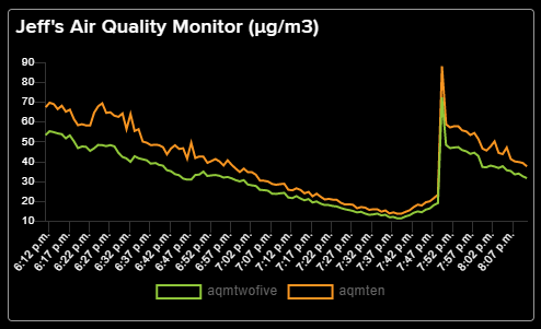
10. If you have everything working as intended, you can configure your script to run at boot by opening crontab
crontab -eand adding the following line
@reboot sleep 60 && python3 /home/pi/air_quality_monitor/aqm.py &
You can exit here, if you chose nano as your editor, by pressing Ctrl + X, pressing Y, and pressing Enter.
Final Touches
Now that your Pi Zero has a script that will interface with the SDS011 sensor, the script runs on boot, and will constantly push the data from the sensor to your adafruit.io dashboard, you can place this device anywhere you need. For my final touches I have been looking into a case for the whole setup and a rechargeable battery but for now it’ll have to do with being plugged in. If you’ve made any improvements or just want to share your build feel free to contact me.